| |
|
|
 |
STEP
1
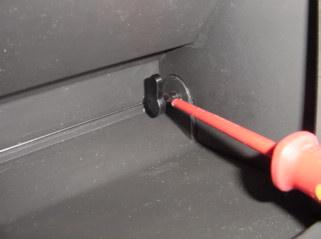
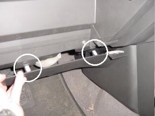
Empty glove box and remove the 2 clips at the bottom (on the
inside).
Use a flat-head screwdriver as shown in Fig.1 to slide them
towards the middle of the glove box.
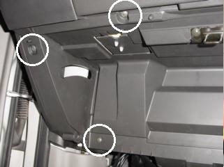
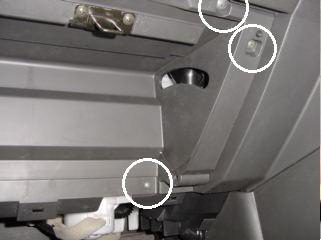
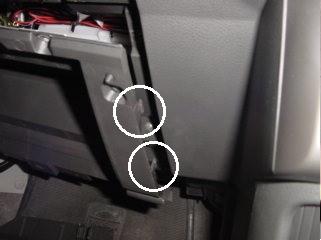
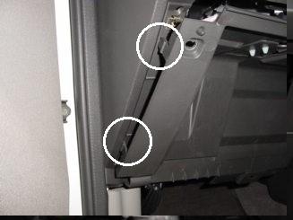
You will need to tilt the glove box to one side to remove it -
see glove box guides in Fig.2 & 3.
Put it in a safe place where it wont get scratched (back seat is
a good spot).
We all know how durable X-trail trim panels are!
|
 |
 |
|
Figure 1 |
Figure 2 |
|
 |
|
|
Figure 3 |
|
|
|
|
STEP
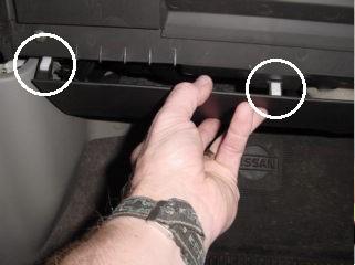
2 Remove the bottom
section of dashboard on passenger�s side as shown in Fig.4 & 5.
Notice the location of the three clips
(left, centre and right).
This panel is quite flexible so it is
easy enough to get your fingers in-between the panel and the
bottom of the glove box panel.
The panel bottom comes out straight
towards you.
 |
 |
|
Figure 4 |
Figure 5 |
|
|
|
STEP
3
Remove the 6 grey
Philips-head screws which hold the glove box frame in place.
There are two on
the top, two on the sides at the top, and two on the bottom near
the ends.
See Fig.2 & 3.
Do NOT remove the two brown screws holding the glove box latch
in place!
|
|
|
STEP
4
There are clips on
both sides of the glove box frame. See Fig.6 & 7 for their
location.
The glove box
frame comes out straight towards you - no tools are needed to
get it out; just pull it carefully.
The panel may
flex a little near the clips, but they aren�t too tight.
 |
 |
|
Figure 6 |
Figure 7 |
|
|
|
STEP
5
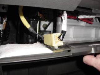
You may have noticed
the connector which is attached to the top of the glove box
frame in Fig. 8 & 9.
I think this is
for the SRS Airbag, so I wouldn�t recommend disconnecting it!
You should be
able to turn the glove box frame panel around so the right hand
side is sitting on the floor close to the passenger�s door as
shown in Fig.10.
Alternatively,
you can use pliers or long-nose pliers to remove the connector
from the glove box frame panel by squeezing the white plastic
clips in Fig.8.
Don�t forget to
put it back when you�ve finished.
 |
 |
|
Figure 8 |
Figure 9 |
|
|
|
STEP
6
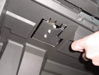
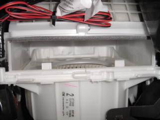
Fig.10 shows the big
white blower motor.
There are two
tabs on the bottom of the filter door which you pull out towards
yourself to remove the door.
Fig.11 shows the
filter door removed, with the slot for the filter to sit in.
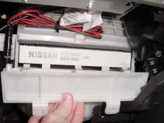
For some reason
(cost-cutting?) Nissan decided not to include one of these
filters as standard.
 |
|
Figure 10 |
|
|
|
STEP
7
Follow the
instructions that come with the filter to install the
self-adhesive foam.
Fig.11 & 12 show
how to put the filter in and replace the filter door.
|
 |
 |
|
Figure 11 |
Figure 12 |
|
|
|
STEP
8
Put all the panels
back on in reverse order. |
|
|
More
information can be obtained in
this thread on the forum. |

